Robotic Bending
Robotic bending provides repeatability, precision and increased safety. The ability to operate ‘lights out’ allows for a fast and cost-effective metal bending, without compromising quality.
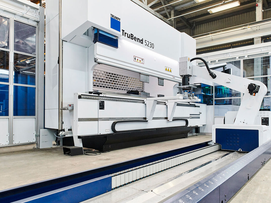
Newfield’s new TruBend Cell 5000 provides productive and flexible automation for a wide range of products, producing them to a consistently high standard. It is capable of producing parts up to 100kg with very precise angles. It is also incredibly efficient and reduces production time while maintaining reliable output and material handling.
Our robotic forming cell is comprised of a Trumpf bending cell – a TruBend 230S. It offers automated tool selection, material loading and a conveyor system for flexible storage. It enables us to perform ‘lights-out’ operations, where the machine is programmed and loaded before being left to run autonomously. Its built-in checks are verified by our engineers using a measurement system analysis (MSA) process.
Metal folding is used to create many products including pipes, enclosures, boxes and more, as sheet metal can be fashioned and reshaped in many ways such as rolling, indenting, bending and shearing.
Newfield’s quality assurance team carry out in-process checks throughout fabrication to ensure repeatable high accuracy, whilst advanced 3D measurement technology guarantees all components meet the very tight tolerances required by our customers.
Learn more about our design considerations for bending work.
More Information
Here at Newfield, we utilise a process known as ‘air bending’ that uses the minimum amount of force possible. This maximises the capability of the press brake while reducing tooling wear.
Bend Radius (Inside Bend Radius)
With air bending, the inside radius is predominantly determined by the die opening (also referred to as V-width). In order to reduce the required force, a larger V-width must be used. Generally, the minimum inside radius is equivalent to the thickness of the material. Because dies are manufactured in specific sizes, generous tolerances should be allowed – up to ± 30%.
Minimum Flange Length
It is recommended that the minimum flange length should be at least four times the material thickness. The V-width of the press brake determines how small the flanges can be. Smaller flanges than this are only possible with additional work, such as forming a larger flange and then machining it down, adding expense. Our team of design engineers will thoroughly analyse the manufacture of a part, including possible tooling, to ensure costs are minimised and the part meets all requirements.
Bend Relief
If a bend is too close to an adjacent edge, the material is likely to tear. To prevent this, the relief length should be greater than the radius of the bend. The width of the relief should also be the equivalent of the material thickness, at least. There are several advantages to a larger bend relief, including ease of component alignment, prevention of crack propagation and the reduction of setup and running costs.
Forming Near Holes
It is recommended that holes are positioned away from bends to avoid distortion. As the material is bent, the hole will deform from its original size and shape, likely preventing it from performing its intended function. Any holes located close to a bend must be created after bending as part of a secondary machining operation. To avoid the associated expenses, any holes or slot edges should be positioned so that they are clear of the die opening when the bend is formed. Generally, this means holes or slot edges must be offset around 3-4 times the material thickness from the bend line.
Bend Edge Distortion
Distortion can be created at the edge of a bend as material thickness increases and the bend radius decreases, this is part of the bending process. If this is unacceptable, then the component can be relieved.
Dimensions
Our engineering team dimensions parts in a single direction, where possible. Due to the sequential nature of the forming process, and the fact that dimensional variations are introduced by each bend, dimensioning in a single direction helps to control tolerance accumulation.
Our Engineering team not only rely on their personal expertise but also “shop-floor” knowledge, collaborating to determine the best tool selection and critically comparing this with what has been recommended by the software. This ensures that the most appropriate tool is used every time and that the parts meet the dimensional tolerances requested by the customer.
If a blank development is required, it should be marked up as ‘For Information Only’. Developments provided by third parties are often created without consideration for the actual press brake tools used during production. To guarantee the desired quality, it may be necessary to generate a blank development to suit the tooling, ensuring that the formed component matches the requirements.